This articles describes how to create and add decals from images to SOLIDWORKS models.
To add a decal to an open SOLIDWORKS model click DisplayManager  >View Decals
  >Open Decal Library.

Then drag and drop the decal from the decal library.
If the desired decal is an image not located in the Decal Library use the following steps:
- Right-click empty space in the DisplayManager and click Add Decals.
- Browse to the desired image file (jpg, png, bmp, etc) on the hard drive.
- Save Decal can be used to make a copy of the original image in a .p2d file type.
- A prompt will appear if the image’s file path is not currently visible by the Decal folder. Clicking “Yes” will allow the file path to be visible from the Decal folders Task Pane.

Once a decal is dragged and dropped into the part file, many options can be adjusted. The next few sections will discuss the various types of options that can be changed for the decal.
Mask Image
In the Image tab several options can be selected for the mask image.
No Mask
Places decal onto model just as the image is.
Image Mask File
- Open an image in a program such as Paint
- Go to File> Save As and change the Save As type dropdown to Monochrome Bitmap
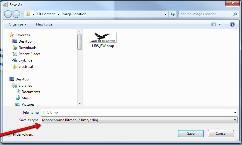
- In SOLIDWORKS, click Browse under Mask File Path and browse to the recently saved out Monochrome Bitmap file
- The Bitmap image has now masked the decal
- Click Invert mask if incorrect portion of the image was masked
Selective Color Mask
Select the Pick Color icon  , then using the
  pointer within the Decal Preview window to select colors to exclude. To remove a color, select the colored rectangle to remove and click Remove Color.
Use Decal Image Alpha Channel
Uses a composite image that contains the decal and a mask. To create the image, click Save Layered Image in the PhotoView Render Frame dialog box and then create a composite image in an external graphics program. Supported file types are .tif and .png. Click Invert mask if incorrect portion of the image was masked.
Mapping
Switching to the mapping tab in the decal property manager and selecting a face(s) to apply the decal to allows adjusting of mapping options.
Label
Also known as UV, maps decals onto model faces, including multiple contiguous non-planar surfaces, in a way that is analogous to placing an adhesive label on a real part, with no stretching or shrinking.
Projection
Maps all points onto a specified plane and then projects the decal onto the reference entity.
Spherical
Maps all points onto a sphere.
Cylindrical
Maps all points onto a cylinder.
Size/Orientation
- Size the decal to desired dimensions by either dragging the boundaries of the decal or entering dimensions into the property manager.
- Rotate the decal by either entering a value into the property manager or clicking the yellow circle and dragging the mouse.

Illumination
Switching to the Illumination tab allows you to change illumination options.
Dynamic Help
Displays pop-up tooltips for each property.
Use Underlying Appearance
Applies the illumination settings from the appearance under the decal to the decal. When cleared, this option sets the illumination for the decal directly and enables the remaining options in this property manager.
Diffuse Amount
Controls intensity of light on a surface. A higher value makes the surface appear brighter.
Specular Amount
Controls the intensity of highlights, making the surface appear shinier. A lower value reduces highlights. Dependencies: Specular Spread must be greater than 0. At least one directional, spot, or point light must illuminate the model and be enabled in PhotoView.
Specular Color
Controls the color of reflected highlights within the specular component. Double-click to select color. Dependencies: Specular Spread and Specular Amount must be greater than 0. At least one directional, spot, or point light must illuminate the model and be enabled in PhotoView.
Specular Spread
Controls the blurriness of reflections on a surface, making the surface appear rough or smooth. Higher values make highlights larger and softer. Dependencies: Specular Amount must be greater than 0. Specular Color must not be black. At least one directional, spot, or point light must illuminate the model and be enabled in PhotoView. When Blurry Reflections is disabled, it affects reflections of physical lights only. When Blurry Reflections is enabled, it includes environmental and self-reflections.
Reflection Amount
Controls the reflectivity of a surface, on a scale of 0 to 1. If set to 0, no reflections are visible. If set to 1, the surface simulates a perfect mirror.
Blurry Reflections
Enables blurring of reflections on surfaces. The level of blurring is controlled by Specular Spread. When Specular Spread is 0, no blurring occurs. Dependencies: Specular Spread and Reflection Amount must be greater than 0.
Transparent Amount
Controls the degree to which light can pass through a surface. Lower values increase the opacity; 0 is completely opaque. Higher values increase the transparency; 100 is completely transparent.
Comments
Thanks! it worked.
Article is closed for comments.