
Problem
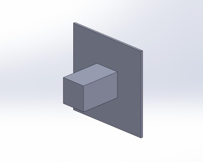
This article describes how to create an Edge Weld Connector between Solid and Shell components in a simulation study. The image below is an example of a model that uses a solid and shell component in a simulation study.
Solution
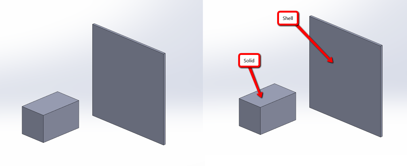
In order to create an Edge Weld connection feature between a solid and shell mesh, an intersecting edge between the solid and shell must be made with a Split Line feature on the shell component. The image below shows the shell and solid components without split lines.
- Right-click on the Shell component in the FeatureManager Tree
- Select "Edit the Part"
- Create a sketch on the face of the shell body that intersects with the Solid body
- Using "Convert Entities", convert the edges of the intersecting Solid body edges
- Exit the sketch
- Select "Split Line" under Insert>Curve
-
Select the sketch made in step 3 and the face of the shell body that intersects with the Solid body

- In the Simulation Study, right-click on Connections
- Select "Edge Weld"
- For Face Set 1: Select the face of the shell.
- For Face Set 2: Select the face on the solid body, which intersects perpendicularly with the shell body
- The Intersecting Edges will automatically generate with the correct selections, and a preview of the Edge Weld Connector can now be seen below.

- Click the Green Checkmark to create the feature
For additional support, existing customers can submit a ticket or new customers can contact Hawk Ridge Systems.
Comments
Article is closed for comments.