The incline plane allows the operator to see positions at the machine that are relative to the model without using new work offsets.
Setting it up
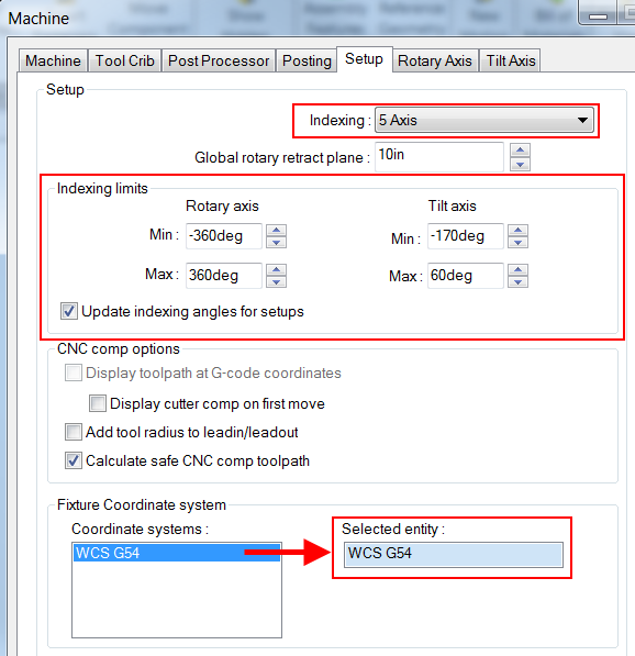
- You must have a machine and post that supports incline plane machining.
- Assembly mode is recommended but not necessary.
- The options that are set up in the machine definition are where everything is referenced from.
How it works
In this example we will be drilling two holes one at the X0, Y0, Z0 location of the G54 fixture offset on the front face of the part. The other hole is on a face at 90 degrees for the original
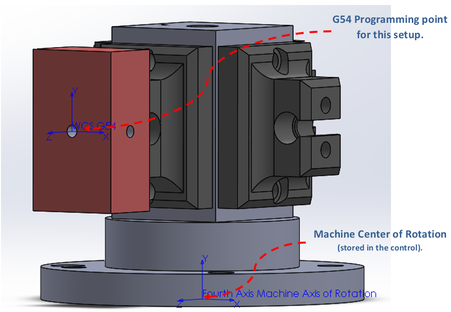
To set these, you will need to create your fixture coordinate system in SolidWorks. Set this coordinate system in the Machine definition and be sure your indexing limits are set based on your machine setup. **This is not the axis of rotation coordinate, as that is stored in your machine’s controller.
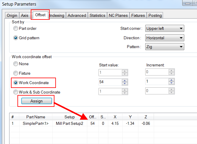
Under the offset tab, select the Work coordinate offset you are looking for, type in the correct number and be sure to press Assign to set the offset on the selected part listed below. After this is selected, you need to set your part coordinate by right clicking on the part setup in your operations tree and choosing edit definition.
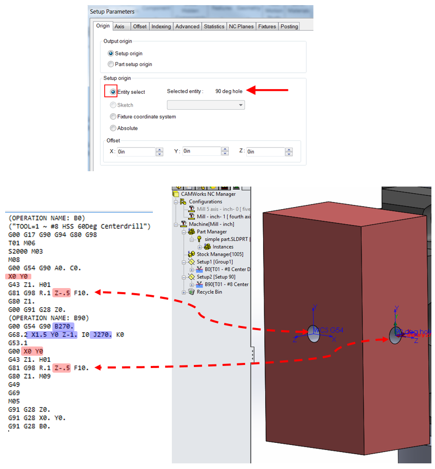
In CAMWorks let’s post a program of just the rotary transformation.
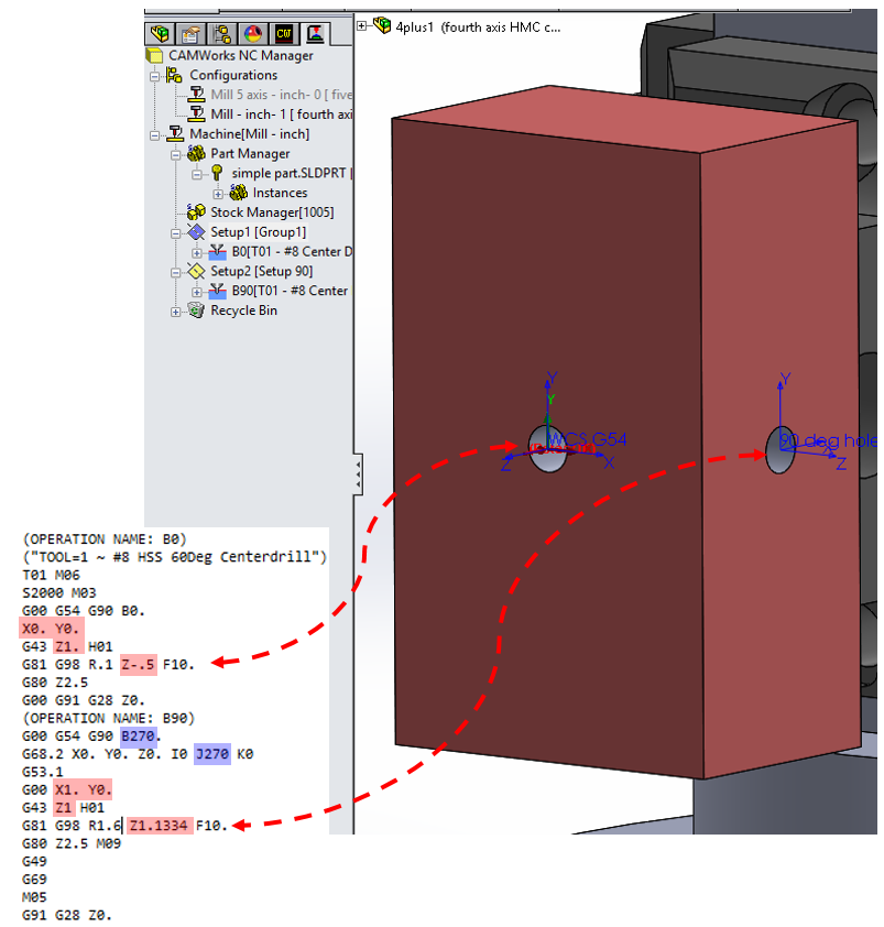
In the above picture notice the X, Y, & Z positions are all referenced from the G54 coordinate. For the 270 degree rotation notice the B index of 270 and the J value on the G68.2 line transforming the plane. However X, Y, & Z are still referencing the G54 coordinate system.
Now let us transform the X, Y, & Z so the values are coming from the holes center at the 270 degree index.
Edit the definition of Setup2 in the operations tree and choose the origin tab. You can select the edge of the hole or select the “90 deg Hole” coordinate system that was created.
For further assistance, please contact our HawkSupport team at 877-266-4469(US) or 866-587-6803(Canada) and support@hawkridgesys.com.
Comments
Article is closed for comments.